
Safety first
Before drilling, check both sides of the wall and consider where electrical, water and gas services may run. Detection tools are helpful but imperfect. Use a stable ladder or platform, wear suitable eye and hearing protection, and control dust. If the wall construction or service location is uncertain, stop and engage an appropriately qualified person.
Before you begin
This guide begins after you have selected your Slimline system. Use the Slimline calculator to confirm track quantities and the Slimline product guide for hanger, hook and load compatibility.
Gallery Systems’ published instructions provide the installation sequence. The Shakespeare Solutions field notes throughout this guide add practical detail learned from installing the system on a wide range of Australian walls.
Tools and protective equipment
- Tape measure and pencil
- Stud finder suited to the wall
- Spirit or laser level
- Drill and material-appropriate bits
- Driver or screwdriver
- 24 TPI or finer hacksaw and a mitre box
- Drop saw with an aluminium blade, if preferred
- Metal file
- Hammer and, if required, a clean plastic mallet
- Stable ladder or work platform
- Vacuum or dust extraction
- Eye and hearing protection plus suitable respiratory protection
Working practically: a two-metre track can usually be installed by one confident person, although a second pair of hands helps. Allow extra time for the first length while you learn how the particular wall behaves. For a long run, a stable work platform can be more practical than repeatedly repositioning a stepladder.
1. Choose the track position
In many environments, the track looks most discreet immediately beneath a straight cornice or square-set ceiling. Before drilling, check every wall where the system will be installed and consider the alternatives below; a ceiling can look straight while varying substantially across a room and throughout the premises.
- Straight ceiling or corniceInstall directly beneath it. If drilling tightly against a square-set ceiling, plan how the drill will reach each fixing position; an offset drill can make this easier and reduce the risk of damaging the ceiling.
- Minor variation of about 2-3 mmA neat caulking bead can conceal small gaps.
- Noticeable waves or curvesDo not force the track to follow them. Establish a deliberate line, often 30-50 mm below the lowest point.
- Very high ceilingConsider keeping the track lower so an average person can reach it safely from a normal stepladder. About 2.6 metres from the floor is often a sensible height. If the track will be installed higher, plan how it will be accessed whenever droppers need to be added or removed.
- Strong architectural lineA door head or former picture-rail height can provide a considered alternative.
Installer’s note: compare a laser line with the visible ceiling line. In an older building, a slight rake parallel to the ceiling can look better than a perfectly level track with a visibly widening gap.
2. Set out one track length at a time
Gallery Systems instruction
Use five wall anchors for each two-metre track and place an anchor at every track join and corner. Read the Track and Wall Anchors instructions (PDF).
Shakespeare Solutions field notes
Work progressively rather than marking the whole room at once. Each wall anchor has two locating tabs at the top. Keep these tabs facing upwards: they can register against a straight hard edge and show where the top of the installed track will finish.
- Position the first track. Hold the first length where it will be installed and mark its far end or join position.
- Plan the anchors for that length. Put an anchor at the join, then use the appropriate plasterboard or masonry method in Step 3 for the remaining positions.
- Install the first length. Fix and align its anchors, then clip the track into place before moving on.
- Continue along the wall. Butt the next length against the installed track, mark its far end or next join and repeat the process. Mark and cut the final length against the actual wall.
- Check the quantity. Five anchors per two-metre track is the recommended minimum. A shortened one-metre section will often use three rather than two.
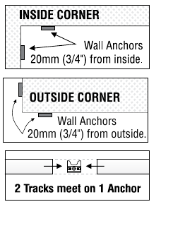
At every join: centre one standard wall anchor behind the join so each track end shares approximately half of the anchor.
3. Fix the anchors for your wall type
Gallery Systems instruction
The manufacturer illustrates each wall anchor secured with a fixing appropriate to the wall. Its plasterboard example uses a screw-in hollow-wall fixing. See the manufacturer’s anchor sequence (PDF).
Shakespeare Solutions field notes
First assess the substrate—the type of wall you are working on—then follow the appropriate route below. Plasterboard on timber or steel studs and solid masonry are the two most common constructions. When the wall construction is unfamiliar, test an ordinary anchor position before drilling a critical join position.
Plasterboard walls
Find the practical studs first. Shakespeare Solutions prefers to fix into every sensibly positioned timber or steel stud, then use suitable plasterboard fixings to support the track between them. This is an additional belt-and-braces preference; the manufacturer permits correct fixing directly into plasterboard.
Timber studs: fix the wall anchor with the supplied 8-gauge screw. Where no stud is available, a small pilot confirms the hollow section before a suitable plasterboard fixing is installed.
Installing a Wallmate accurately: nylon Wallmates suit ordinary plasterboard. Start with a small pilot hole to confirm that no stud is present, then use a drill bit approximately the same width as the Wallmate’s cutting tip to form an accurately centred opening before driving it. This helps prevent the Wallmate wandering away from the intended anchor position.
Steel studs: a StudBuddy magnetic stud finder is particularly useful. Start with a 2 mm pilot, enlarge it to about 2.5-3 mm, then drive the 8-gauge screw. Make the first test fixing away from a join so a broken bit or screw does not compromise that essential position. Carry spare 2 mm bits when installing a longer run: drilling through plasterboard dust and then into steel can wear these small bits quickly.
Fire-rated or acoustic board: nylon Wallmates can crack in these harder boards. Use a zinc Wallmate or another fixing approved for the substrate; we often use TOX Deco 6/41 all-purpose wall plugs in this situation.
Square-set plasterboard: the junction where the wall meets the ceiling is often reinforced with pressed-metal corner bead. A Wallmate cannot be installed through this bead. In this situation, drill an accurate opening and use a TOX Deco 6/41 plug, following the fixing manufacturer’s current drill and screw specifications.
Masonry and brick walls
Position the anchors evenly, retaining the required anchor at each join. Use a rotary hammer with a suitable SDS masonry bit; a four-point bit tends to wander less. Hold dust extraction directly beneath the hole, especially where red-brick dust could mark a pale wall.
Use a wall plug suited to the substrate. Shakespeare Solutions commonly uses TOX Deco 6/41 all-purpose wall plugs. Start smaller in friable old brick or unstable render and enlarge carefully. In hollow brick, select a fixing designed to expand or knot behind the hollow section.
If a plug spins in old, powdery brick: remove the plug if possible and clean the hole. We will often place hot-melt glue in the hole and then push the wall plug back into position. The glue holds it while the screw expands the plug. If this happens repeatedly, reduce the drilled-hole diameter or reconsider the drilling and fixing method.
Near a square-set masonry ceiling, check tool clearance before committing to the track height: the body of a rotary hammer may prevent drilling immediately beneath the ceiling.
Other wall surfaces
Lath and plaster: do not screw a Wallmate into this brittle material. Start with a 2 mm pilot and drill slowly. If the hole reaches sound timber lath, fix into it. If it passes through a gap between the laths, moving the anchor slightly left or right may locate timber. Where the anchor must remain in that position, carefully enlarge the opening and install a TOX Deco 6/41 plug. The construction behind old lath and plaster can be difficult to assess, so the capacity of this fallback fixing is less certain; use conservative judgement and do not rely on it for a demanding load.
Tiled surfaces: pass through the tile slowly with a tile-appropriate diamond bit or hole saw, then identify the substrate behind it. Select the fixing for that material rather than treating the tile as structural.
4. Cut and join the track
Gallery Systems instruction
The manufacturer permits the aluminium track to be cut to the required length and shows the standard join arrangement. Refer to the Track and Wall Anchors instructions (PDF).
Shakespeare Solutions field notes
Measure for ordering, but mark final cuts against the actual wall as the installation progresses. Walls and corners are rarely exact.
- Mark the fitted length. At a perpendicular wall, reverse the track against the wall and transfer the cut position, allowing about 1 mm tolerance.
- Support it securely. Use a mitre box for a hand cut or clamp the track securely for a powered cut. Protect the visible powder-coated face.
- Make a cool cut. Use a 24 TPI or finer hacksaw, or a drop saw fitted with an aluminium blade.
- Finish a cut end. Remove burrs with a metal file and make sure the cut is square.
Joining two lengths: the powder-coated factory ends can be joined as supplied. For the neatest joint, remove the coating at the meeting ends by trimming approximately 0.5-1 mm with a drop saw fitted with an aluminium blade, or by carefully filing away the coating. The aim is simply to remove the powder coating and true the edge. Line the two lengths up before installation and confirm the ends meet squarely and cleanly.
Do not use an abrasive hot saw intended for steel. Heat can damage the aluminium track’s powder-coated finish.
5. Finish corners and uneven walls
Gallery Systems instruction
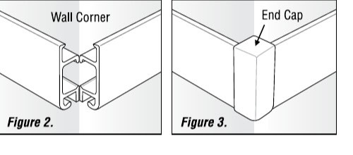
At an outside corner, two square-cut track ends meet and one Slimline end cap covers the junction. Read the End Caps instructions (PDF).
Shakespeare Solutions field notes
Inside corner: run one track to the perpendicular wall and butt the second against it. End caps are normally unnecessary. Avoid mitres; this small profile makes inaccuracies obvious.
Outside corner: finish both tracks flush with the wall edges and use one end cap to cover the meeting ends.
6. Snap on the track and fit the end caps
Gallery Systems instruction
Clip the track progressively over the installed anchors, then fit the end caps in the orientation shown by the manufacturer. Track instructions End cap instructions.
Shakespeare Solutions field notes
- Check every anchor. Confirm it is secure, aligned and installed with the two locating tabs facing upwards.
- Start just clear of a perpendicular wall. Position the track about 2-3 mm from the wall and tap it onto the first anchors. Once engaged, slide it gently towards the wall. This helps prevent the end of the track grazing the finished surface.
- Work progressively along the track. Tap the visible face into place using the flat edge of your hand. A clean plastic mallet can be used gently where necessary.
- Inspect and finish. Confirm the track has engaged every anchor, then insert the end cap with its curved section at the bottom.
7. Add droppers, hooks and artwork
Gallery Systems instruction
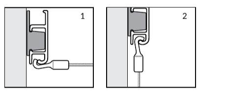
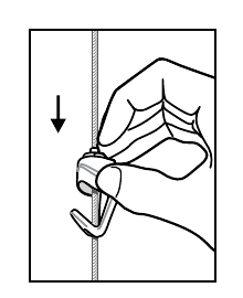
Insert the selected hanger into the track and use the matching hook as illustrated in the component sheets. Review the applicable instructions before use: clear tape and stainless cable, Mini Hook and Push Button Hook.
Shakespeare Solutions field notes
Insert the clear tape, Clearline or stainless-steel cable hanger into the track horizontally, then rotate it down. Refer to the product guide for compatibility and weight limits.
- Single hanging: place one hook beneath the centre of the picture wire.
- Double hanging: use two D-rings or equivalent mounting points. Do not place two hooks on one wire; they can creep towards the centre.
- Use two droppers when approaching a single-dropper limit, when the artwork needs help staying level, for visual balance, or where it may occasionally be disturbed.
- Do not add a third dropper to gain capacity. Sharing the load evenly across three is unreliable. If two correctly rated droppers are insufficient, use another method such as a Z Bar or French cleat.
As a starting point, position the centre of the artwork at approximately the viewer’s eye height, then adjust it to suit the room. The system is designed to make this easy. When changing artwork, inspect the droppers and hooks for visible damage before reuse; no other routine maintenance is normally required.
Troubleshooting
The ceiling is wavy and gaps appear above the track
Small gaps of about 2-3 mm can often be caulked. For larger variations, sit the track a deliberate distance below the ceiling or cornice and keep that distance consistent along the wall. The intentional gap helps minimise the visible imperfections above it.
The track will not clip onto an anchor in a wall depression
If the wall moves in and out, an anchor positioned in a local depression may sit too far back for the track to engage correctly. Remove that anchor and pack it out slightly so its face aligns with the surrounding anchors, then refit it. Once the track is installed, the small packer will usually be concealed.
I need to remove an installed track
Removal is possible but can be difficult. Follow our separate guide to removing Slimline track.
Manufacturer instructions
Keep the original Gallery Systems sheets with the system for their diagrams and component instructions.
- Track and wall anchorsPDF
- End capsPDF
- Clear tape and stainless cablePDF
- Mini HookPDF
- Push Button HookPDF
If the wall construction is uncertain or this kind of work is not for you, find an authorised Gallery Systems installer.